Overview of the ARC AV 401V Video Subsystem
The ARC AV 401V Video Subsystem is a licensable core targeting system-on-chip designs incorporating multi-standard video and image decoding applications. Information on the ARC AV401V is available at: http://www.arc.com/subsytems/video.html.
 BDTI H.264 Decoder Benchmark Certified Results
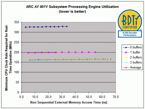
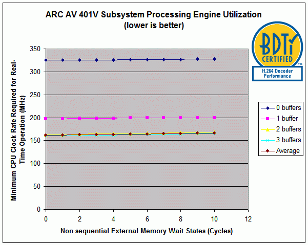
In this report, H.264 decoder solution performance is reported as the minimum clock rate required to decode BDTI’s Primary Operating Point H.264 bitstream in real-time. Two important factors that affect the minimum required clock rate are the number of output “delay buffers” used and the performance of external (main) memory. In recognition of these factors, BDTI has chosen to present the minimum clock rate required by the ARC AV 401V Subsystem for real-time operation for a number of output delay buffer sizes and a range of external memory access times (see Figures 1 and 2).
In the figures, “0 buffers” (i.e., no buffering of output frames) indicates the clock rate required to process the single most processing intensive frame in the video clip in real-time (i.e., 1/30th of a second). Adding delay buffers (each of which holds one decoded frame) smoothes the processing load across multiple frames and significantly reduces the required clock rate. For the ARC AV 401V Subsystem, using three buffers results in a minimum required clock rate essentially equal to the minimum clock rate achievable (i.e., the average per-frame processing over the entire video clip).The 3-buffer case is the typical output buffering used in real-world applications; the 0-buffer case is not typical and would only be used in extremely delay sensitive applications.
BDTI uses the three parameters identified below when describing the external memory access timing characteristics of a device undergoing certification on the BDTI Solution Benchmark for H.264 Decoders. In these descriptions we use the term “burst” to refer to a sequence of accesses to words located in consecutive memory locations (where the size of each word is the equal to external bus width). For DSP-intensive algorithms such as H.264, external memory accesses are often made in bursts.
1. Memory-Processor clock ratio: This is the ratio of the processor speed to the maximum external memory speed. For example, a Memory-Processor clock ratio of 1 indicates that the processor and memory operate at the same speed (i.e., the external memory is capable of supporting an access every processor clock cycle). However, a memory-processor clock ratio of 3 combined with a 300 MHz processor clock speed would result in a 100 MHz external memory speed (i.e., each external memory access requires a minimum of 3 processor clock cycles).
2. Non-sequential external memory stall multiplier: This number multiplied by the memory-processor clock ratio results in the latency associated with accessing a random memory location (e.g., the first access in a burst) measured in processor clock cycles. For example, if the memory-processor ratio is 6 and the non-sequential external stall multiplier is 5, then each non-sequential memory access will require 30 processor clock cycles.
3. Sequential external memory stall multiplier: This number multiplied by the memory-processor clock ratio results in the latency associated with accessing a sequential memory location (e.g., in a burst access, all subsequent contiguous accesses after the first non-sequential one) measured in processor clock cycles. For example, if the memory-processor ratio is 6 and the sequential external stall multiplier is set to 1, then each sequential memory access will require 6 processor cycles.
These parameters provide a reasonable first-order model for the performance of a solution using typical external memory devices, such as DDR2. However, the actual memory controller used in a final system may have different characteristics, and thus impact the performance of a solution.
The table following the figures summarizes the complete results for the device on the BDTI Solution Benchmark for H.264 Decoders and shows the solution clock rate required only for the minimum external memory access times reported.
Figures 1 and 2 show the minimum solution clock rate required for real-time operation, where lower is better. The only difference between Figures 1 and 2 is in the expression of the external memory access delays. In the first graph, external memory access delay is expressed in time (ns), and in the second graph delay is expressed in wait states (clock cycles). Note that since the memory-processor clock ratio is 1 in all cases for the ARC AV 401V, the non-sequential and sequential external memory stall multipliers will be equal to the non-sequential and sequential memory wait states, respectively.
For more information about the metrics reported for the Solution Benchmark for H.264 Decoders click here.

Figure 1: ARC AV 401V Subsystem Processing Engine Utilization vs. External memory Access Time. Note that since the memory-processor clock ratio is 1, the non-sequential external memory access time is equal to the non-sequential external memory stall multiplier divided by the clock rate. The following parameters are constant for all “Non-sequential external access times” values shown in the above graph: Memory-processor clock ratio: 1; Sequential external memory stall multiplier: 1.

Figure 2: ARC AV 401V Subsystem Processing Engine Utilizaiton vs. External Memory Wait States. Note that since the memory-processor clock ratio is 1, the non-sequential external memory wait states is equal to the non-sequential external memory stall multiplier. The following parameters are constant for all “Non-sequential external wait states” values shown in the above graph: Memory-processor clock ratio: 1; Sequential external memory stall multiplier: 1.
| ARC AV 401V Video Decoder Performance on the Solution Benchmark for H.264 Decoders Baseline Profile, D1 (720x480) Resolution, 30 fps, 1.5 Mbps |
||||||
|---|---|---|---|---|---|---|
| Metric | Minimum Clock Rate (MHz) | External Memory Bandwidth (MBytes/s) | Program Memory Usage (KBytes) | Static Data Memory Usage (KBytes) | Dynamic Memory Usage (MBytes) | Buffering Delay (seconds) |
| Average over entire clip | 161 | 63 | 89 | 17 | N/A | N/A |
| Buffering 3 frames | 161 | 64 | 89 | 17 | 6.0 | 0.100 |
| Buffering 2 frames | 162 | 65 | 89 | 17 | 5.5 | 0.067 |
| Buffering 1 frame | 197 | 67 | 89 | 17 | 5.0 | 0.033 |
| No buffering—highest CPU load frame | 324 | 72 | 89 | 17 | 4.5 | 0 |
| Estimated energy consumption | N/A | |||||
| Cost (silicon area) for licenseable IP | N/A | |||||
| Cost (dollars) for chips and external devices | External 32-bit memory required; cost depends on type and latency of memory chosen | |||||
No reproduction or reuse of the above information is permitted without the express authorization of BDTI. For reproduction permission or to obtain benchmark results for your processing engine, please contact BDTI.
